When designing injection-molded components, one detail consistently separates efficient, scalable production from costly manufacturing headaches: the draft angle. At LSRmold, we’ve supported thousands of injection-molding projects across consumer goods, automotive, medical, and industrial sectors. One pattern is unmistakable—designs with proper draft angles mold cleanly, run faster, and create far fewer complications. Designs without them? They often stall production, damage molds, increase rejection rates, and frustrate customers.
If you’re developing a new plastic part or optimizing an existing design, this guide will give you a practical, engineering-backed understanding of draft angles—what they are, why they matter, and how to apply them correctly. As a professional manufacturer and supplier offering high quality tooling and OEM services, LSRmold created this guide to help customers achieve smooth mold release, better part consistency, and lower production costs.
What Is a Draft Angle?
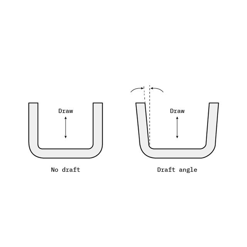
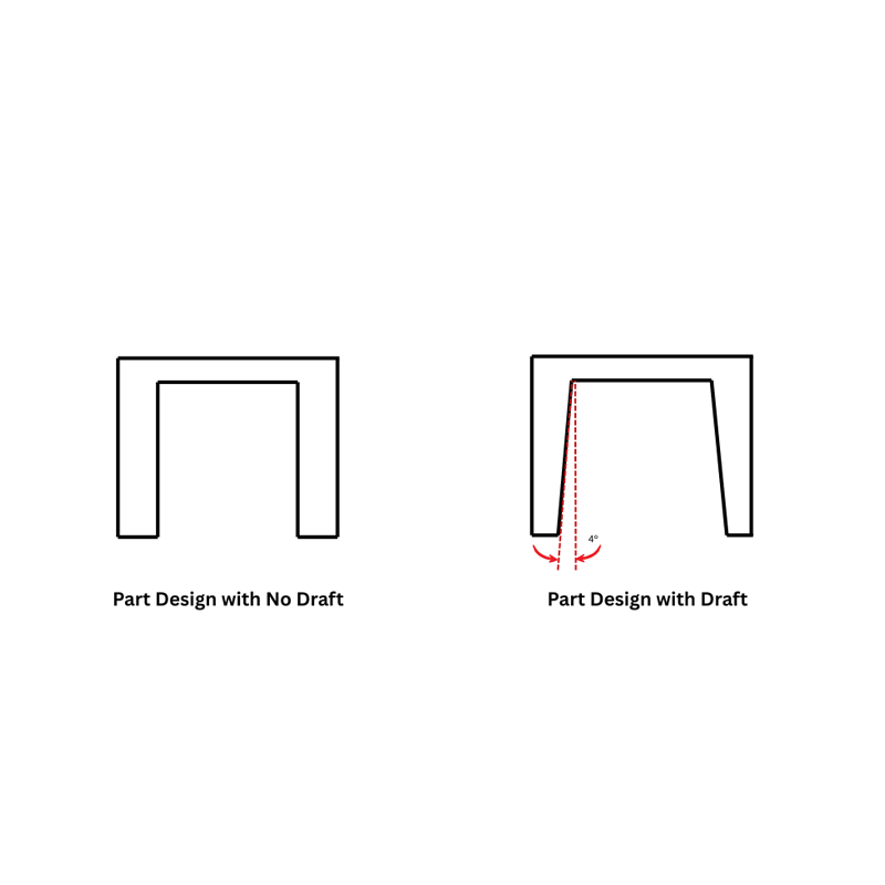
A draft angle is the slight taper applied to the vertical walls of an injection-molded part. It ensures the part can be released smoothly from the mold cavity without scraping, sticking, or causing friction damage.
Imagine molding a plastic cup. If its walls were perfectly straight, the cup would create a vacuum-like grip against the mold core. A draft angle eliminates that grip by widening the opening just enough for a clean, controlled release.
In essence, draft angles are:
- Essential for mold longevity
- Necessary for efficient ejection
- Critical to surface and dimensional quality
- A foundational part of DFM (Design for Manufacturability)
Without drafts, every production cycle becomes more difficult, less predictable, and more expensive.
Why Draft Angles Matter in Injection Molding
Draft angles directly influence:
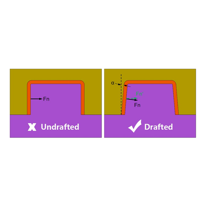
1. Smooth Part Ejection
Draft reduces friction during ejection, minimizing mechanical force and preventing deformation or cracking.
2. Reduced Tool Wear
Every time a part sticks to the mold, friction damages critical tooling surfaces. Draft angles keep molds running longer and reduce maintenance downtime.
3. Faster Cycle Times
Clean release = faster mold opening, quicker ejection, and shorter overall cycle times.
4. Improved Surface Finish
Parts without proper draft suffer from drag lines, scratches, and distorted textures.
5. Lower Scrap Rates
Better release equals fewer damaged parts—which means better yield and lower cost per part.
6. Greater Dimensional Stability
A correctly drafted part maintains its intended shape without distortion during ejection.
When LSRmold evaluates customer designs, draft is one of the first items we review because insufficient draft causes more production delays than almost any other design oversight.
Draft Angle Best Practices
1. Minimum Recommended Draft: 1.5°–2°
For parts with mold depths up to 50 mm, a minimum of 1.5° to 2° is required.
At LSRmold, our engineers often recommend 2° or more to guarantee smooth release, especially when the part has complex geometry or a textured finish.
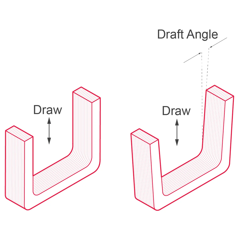
2. Draft Must Follow Mold Opening Direction
Draft must always align with the direction in which the mold opens.
Example:
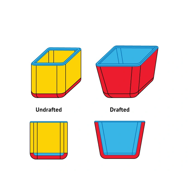
For a box-shaped part:
- The bottom is narrower.
- The top is slightly wider.
- The draft runs upward, toward the opening direction.
Failure to follow this principle often results in sticking, especially on the core side.
3. Add 1° Draft for Every 25 mm of Depth
Deeper features create more surface contact and more friction.
Rule of thumb:
For every 25 mm (1 inch) of depth → add at least 1° of draft.
Example:
| Feature Depth | Minimum Draft |
|---|---|
| 25 mm | 1° |
| 50 mm | 2° |
| 75 mm | 3° |
This simple rule dramatically improves release consistency.
4. Increase Draft for Textured Surfaces
Textures increase friction and require additional draft.
| Surface Finish | Recommended Draft |
|---|---|
| Polished | 1°–2° |
| Light Texture | 3° |
| Medium Texture | 4° |
| Heavy Texture | 5° or more |
Texture depth should always be measured in microns and validated with your mold supplier. At LSRmold’s factory, we provide texture compatibility checks for all OEM tooling projects.
5. Consider Material Shrinkage and Flexibility
Different polymers behave differently as they cool.
| Material | Minimum Draft | Recommended Draft | Notes |
|---|---|---|---|
| Nylon (PA) | 0° | 1° | Flexible, releases easily |
| PE | 0.5° | 1.5° | Low shrink |
| PVC | 0.5° | 1.5° | Rigid, slightly higher friction |
| PP | 1° | 2° | Moderate shrinkage |
| PC | 1.5° | 2° | Brittle, prone to drag marks |
Materials with higher shrinkage or stiffness require larger drafts to prevent sticking.
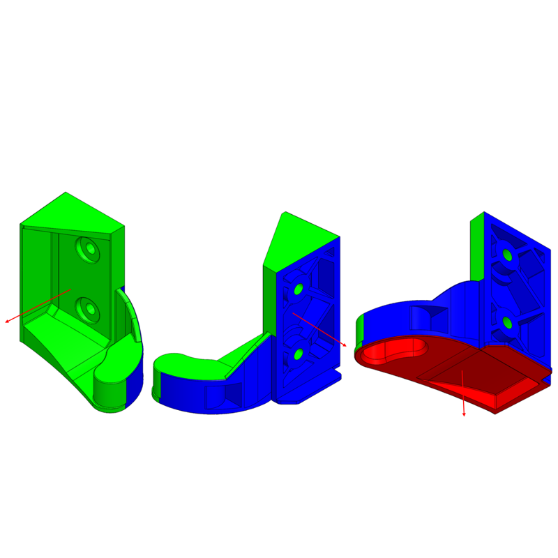
6. Draft Every Mold-Contacting Feature
Draft is not only for the outer walls.
Apply draft to:
- Ribs
- Bosses
- Gussets
- Louvers
- Internal cores
- Any structural feature touching the mold steel
| Feature | Recommended Draft |
|---|---|
| Ribs | ≥ 0.5° |
| Boss Inner Diameter | ≥ 0.25° |
| Boss Outer Diameter | ≥ 0.5° |
| Gussets | ≥ 1° |
Even the smallest undrafted feature can cause major production issues.
7. Dual-Sided Draft for Symmetrical Parts
For symmetrical components (e.g., cylindrical or domed parts), both sides of the parting line require draft, since each side releases independently.
This ensures equal distribution of ejection force and prevents warping or sticking.
8. Never Use Zero Draft Unless Absolutely Necessary
Zero-draft walls are almost always problematic.
If you must use zero draft due to strict design requirements:
- Expect higher tooling costs
- Expect increased maintenance
- Expect more elevated ejection force
Even 0.5° can significantly improve mold release.
Common Mistakes Designers Should Avoid
These are mistakes we frequently see when working with new customer designs:
- Forgetting to add draft on deep interior walls
- Not applying draft early in CAD modeling
- Failing to account for textures or coatings
- Using identical draft for every material type
- Overlooking draft for ribs or bosses
- Designing vertical walls that are impossible to eject
At LSRmold, our engineering team and tooling specialists perform free DFM analysis to help customers avoid these issues before cutting steel.
Expert Recommendations from LSRmold’s Engineering Team
Integrate Draft Early
Never add draft at the last minute—early drafting avoids expensive redesigns.
Conduct a DFM Review
Before mold manufacturing begins, a DFM check will highlight:
- Insufficient draft
- Release direction conflicts
- Ejection challenges
- Tooling risks
Collaborate with Your Manufacturer
Your supplier and manufacturer understands mold behavior best. Discuss parting lines, draft angles, and ejection methods during early design stages.
Prototype Before Tooling
Rapid prototypes or soft molds help verify draft and release before full-scale production begins.
Quick Reference Table
| Factor | Recommended Draft |
|---|---|
| Smooth Surface | 1°–2° |
| Light Texture | 3° |
| Heavy Texture | 5°+ |
| Deep Cavities | 3°–4° |
| PP/PC Materials | 2° |
| Ribs & Bosses | 0.25°–0.5° |
Conclusion
At LSRmold, we work closely with customers worldwide to ensure every injection-molded part meets high-quality standards before entering mass production. Proper draft angle design is not just a technical preference—it’s the foundation of reliable molding, long-lasting tooling, and cost-efficient manufacturing.
If you’re currently developing a part or reviewing a tooling design, feel free to reach out to our engineering team. As a professional factory, manufacturer, and supplier offering OEM service and high precision tooling capabilities, LSRmold is always ready to support your project with expert recommendations and real-world manufacturing insights.
Would you like us to help evaluate your CAD file for draft angles or provide a free DFM analysis? Just let me know—I’m here to help you build a better, more manufacturable product.